|
More Flexibility in Chain Sling Uses
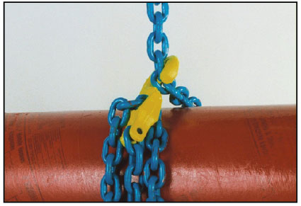
When GrabiQ legs are furnished with chain pockets, chain slings can be used for a much wider variety of loads, often reducing the amount of on-site rigging. Chain pockets can be used to either shorten a leg or create a leg loop. Some GrabiQ fittings are equally well suited for use at the top or bottom of a chain sling. GrabiQ C-Grab fittings can be used as a top-of-the-sling connector or at the bottom of the sling as an adjustable sliding choker.
Quality Standards
Gunnebo Grade 100 GrabiQ alloy steel chain and chain sling components are manufactured and tested in accordance with ASTM A973, A952 and A907 material standards.
|
 |
|
GrabiQ chain and components meet or exceed the safety standards as prescribed by ASME B30.9, B30.10 and OSHA 1910.184-Alloy Steel Chain Sling regulations.
All chain and components are proof tested to 62% of the minimum ultimate strength for the GrabiQ system.
The Swedish plants manufacturing GrabiQ products are certified to ISO 9001/ISO 9002 Quality Standards.
Gunnebo’s quality management covers all aspects of production from raw materials to delivered product.
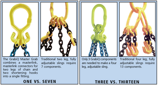
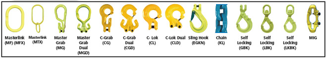
GrabiQ is an exciting new family of alloy chain sling components. Instead of the old “one component does one job” fitting approach, GrabiQ combines in a single component up to three separate functions. The GrabiQ Master Grab combines a masterlink, connecting links for two legs of chain and shortening hooks for each leg, in one fitting. Using traditional fittings to construct the same sling would require seven components, instead of just one. Some new GrabiQ fittings are equally well suited for use as top assembly connectors or as hooks at the bottom of a sling, adding even more versatility. Each leg of a GrabiQ sling is typically furnished with a chain pocket, which can be used for shortening or creating leg loops.
Increased Strength to Weight Ratio with GrabiQ-Grade 100
While the specific Work Load Limits vary, depending on size, slings fabricated from Grade 100 chain and fittings are about 25% stronger than Grade 80 counterparts. Converting from Grade 80 to GrabiQ (Grade 100) will benefit users who can make use of the additional WLL without the expense of purchasing larger chain and fittings. The percentage of strength increase varies depending on the size. Work Load Limit (WLL) gain for 3/8” is about 24 percent, while the WLL for 7/32” is more than 30 percent. All other sizes fall somewhere between.
|
Fewer Components Means:
|
Less Weight & Clutter
|
Easier Rigging & Inspection
|
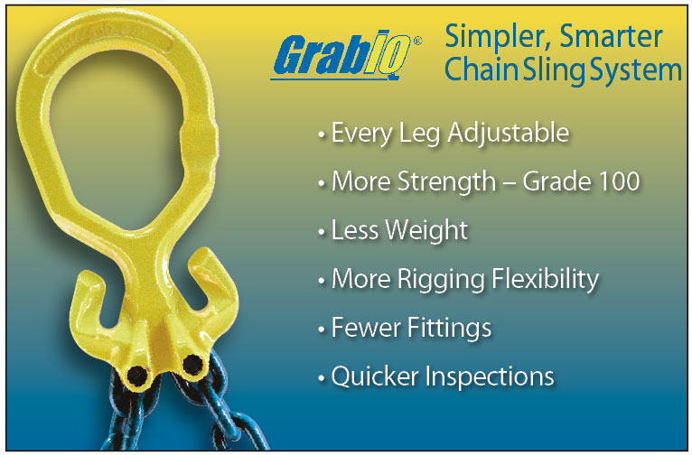
Most of the time, GrabiQ slings will be lighter than Grade 80 counterparts. Fewer components mean less weight and clutter and much easier rigging. Inspecting chain slings is easier and faster because fewer components must be examined for wear or damage.
|
|
| GrabiQ® Warning and Use Limitations |
 |
|
For additional, important information for proper sling use and user safety, refer to:
If you are not trained and knowledgeable, do not use any rigging product.
GrabiQ components shall be used only with Gunnebo Grade 100 Alloy Steel Chain.
Product identifier is forged into GrabiQ sling components and is designated as:
GrabiQ-(Model Designator) – (Trade Size) – (Grade) Example: GrabiQ-MG-13-10.
Never overload a sling. Also read and understand the following: "Never overload a sling by understanding Work Load Limits"
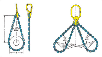
Gunnebo GrabiQ Grade 100 Alloy Steel Chain Sling Work Load Limits (WLL) for selected working ranges of symmetrical sling leg angles are listed in pounds and given in TABLE 1B. No chain sling shall be rigged with a leg angle less than 30° from the horizontal.
Double Leg Sling WLL for an alternate working range of symmetrical sling leg angles equals:
2 X TABLE 1B single leg WLL X sine of the minimum working range angle.
Triple and Quadruple Leg Sling WLL for an alternate working range of symmetrical sling leg angles equals:
3 X TABLE 1B single leg WLL X sine of the minimum working range angle.
TABLE 2, lists the sine values for selected sling legs angles.
Multi Leg Sling WLL for non-symmetrical loading can only be determined by engineering analysis of the
specific rigging condition. In the absence of an engineering analysis, WLL shall be equal to single leg sling WLL given in TABLE 1B..
Choked endless chain sling WLL for selected working ranges of symmetric leg angles are listed in pounds and given in TABLE 4B.
Choked chain sling WLL is affected by choke and choke angle. TABLE 3B illustrates choke angle and reduced Choker Work Load Limits as a percentage of the Single Leg (Vertical) WLL.
|
|
|
|
Gunnebo GrabiQ Grade 100 “Loop Leg” Sling Work Load Limits for selected working ranges of symmetrical sling leg angles are listed in pounds and given in Table 1B. A “Loop Leg” hitch is a type of basket hitch made with a single GrabiQ fitting having an integral chain pocket. The Loop Leg Hitch included angle is limited to a maximum of 30° and shall not be rigged with a leg angle less than 45° from horizontal as illustrated. Sling leg angle is defined by the leg of the “Loop” with the smallest angle.
A basket hitch made with both chain ends terminated by a GrabiQ Clevis connection on the same fitting or
to a separate fitting is a conventional basket hitch and is illustrated.
Gunnebo GrabiQ Grade 100 Conventional Basket Sling Work Load Limits for selected working ranges of symmetrical sling leg angles are listed in pounds and given in Table 1B. Conventional basket hitches are limited to single and double leg slings and shall not be rigged with a leg angle less than 30° from the horizontal.
|
| GrabiQ® Warning and Use Limitations |
|
Never ride a sling or a load. Read and understand the following: <br/ > GrabiQ alloy steel chain slings shall not be used to rig personnel platforms.
<br/ > Self-Locking hooks shall not be used in personnel lift systems unless complying with applicable federal or local lift system and fall arrest regulations. See TABLE 3A.
<br/ > Never rig a sling to a load improperly. Avoid dropped loads and sling damage. <br/ > Refer to Safe Operating Practices per: OSHA 1910-184 (C), ASME B30.5-3.2 and ASME B30.9-1.9:
Load shall be centered in the base (bowl/saddle) to prevent point loading of the hook. See Figures 1a 1b and 1cb.
Hooks shall not be used in such a manner as to place a side load or back load on the hook. See Figures 2a and 2b.
When using a device to close the hook throat opening, care shall be taken so that the load is not carried by the closing device. See Figures 3a and 3b.
<br/ > Hands, fingers and body parts shall not be placed between the sling and the hook and/or load.
<br/ > The use of a hook with a latch does not preclude the inadvertent detachment of a slack sling or a load from the hook. Visual verification of proper hook engagement is required in all cases.
<br/ > Self-locking hooks shall be locked during use.
<br/ > ASME B30.10-1.3 states, “When a hook is equipped with a latch, the latch should not be restrained from closing during use.”
<br/ > Hooks shall not be rigged with more than two (2) sling legs in the hook saddle and sling leg angles shall not be greater than 45° from hook centerline. See Figure 1b.
<br/ > Hooks shall be rigged with a masterlink or shackle when three (3) or more sling legs are used or sling leg angles exceed 45° from hook centerline. See Figure 1c.
<br/ > Sling leg angle shall not be less than 30° from the horizontal.
<br/ > Slings shall only be shortened with a shortening fitting and not shortened with knots, bolts or other makeshift devices.
<br/ > Sling legs shall not be kinked or twisted.
<br/ > Sling hooks shall not be point loaded.
<br/ > Sling hook latch may be mandatory by regulation, safety codes or insurance requirements.
<br/ > Slings used in a basket hitch shall have the loads balanced to prevent slipping.
<br/ > Slings shall be securely attached to their loads.
<br/ > Slings shall be rigged to prevent chain from sliding over a load edge while lifting.
<br/ > The maximum number of GrabiQ fittings to be connected to a masterlink is three as illustrated here. See Figure 1..<br/ > <br/ >
|
 |
|
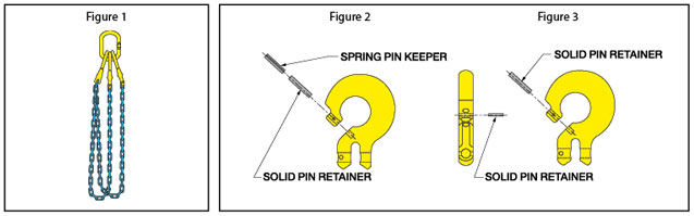
Sling shall not be used unless the GrabiQ coupler of at least one end of each chain leg is secured to the masterlink by one of the retainer and keeper methods illustrated in Figures 2 and 3.
Free end of sling leg when connected to a masterlink with a GrabiQ coupler does not require a retainer. However, either method illustrated in Figure 2 or 3 may be used when desired.
|
| GrabiQ® Sling Assembly Guidelines |
 |
- It is a common practice, when possible, to keep all hooks in the same plane as the masterlink. This is easily accomplished on 1, 2, and 4 leg slings. It is not possible with 3-leg GrabiQ slings when single and dual fittings are mixed.
- It is a common practice, when possible, to attach hooks so that latches point away from the masterlink.
- Mixing GrabiQ fittings: Adding two additional chain links to CL and CLD components gives the same effective reach as CG and CGD. MG and MGD components have the same effective reach.
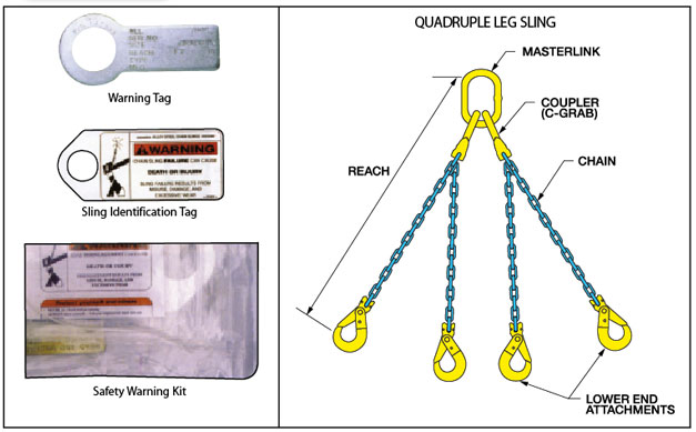
- Metal ID tags must always be attached to a chain sling, showing serial number, size, reach, Work Load Limit at angle of lift and manufacturer. Sling Warning Tags must also be attached. If these are missing, do not use the sling and contact us for replacements. Hook latches must be present and operational. If these are not functioning properly contact us for replacements.
- The reach of the sling is the length measured from the load-bearing surface of the masterlink or top fitting to the load-bearing surface of the hook or lower terminal (as shown in illustration).
- Normally, the masterlink will have a maximum of two connecting links: CG, CGD, CL or CLD. The maximum number of connecting links that can ever be mounted on a single masterlink is three, when constructing a double leg basket.
- A GrabiQ sling can never have more than four independent legs or two basket legs.
- Attaching CG, CGD, CL and CLD connectors to MF, MFX and MTX Masterlinks: Insert the connector onto the masterlink at the engineered flat. C-Connecting links are normally attached to the masterlink using the Dismountable Connecting Set type CS or the Permanent Connecting Set type CP. Each C-Connector includes: one solid retainer pin, one larger rolled spring keeper pin and one smaller rolled spring keeper pin. When the dismountable connecting set is used, the sling can be disassembled for repair. The permanent connecting set cannot be disassembled for repair.
- CS: First install the solid retainer pin and then drive the smaller rolled spring keeper pin through the hole provided, at a right angle to the solid retainer pin. The fit should be very snug.
- CP: First install the solid retainer pin and drive the larger rolled spring keeper pin into the same hole, directly behind solid retainer pin. The fit should be very snug.
|
| GrabiQ® Popular Sling Models |
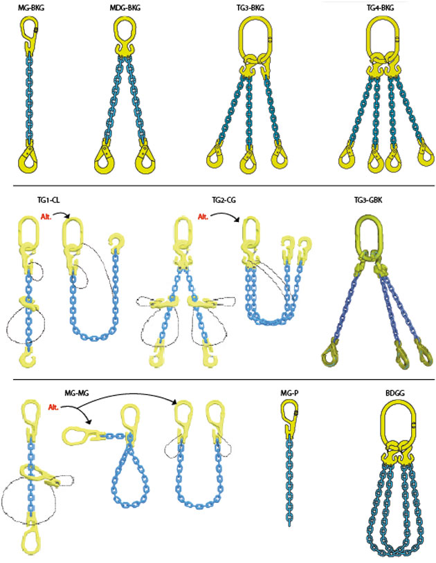 |
|
|