Crosby® Forged Eye Bolt Warnings IMPORTANT INFORMATION: READ, UNDERSTAND AND FOLLOW. IMPORTANT INFORMATION: READ, UNDERSTAND AND FOLLOW.
| 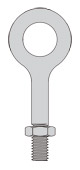 | 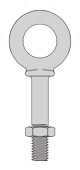 | 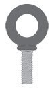 | Regular Nut Eye Bolt G-291 | Shoulder Nut Eye Bolt G-277 | Machinery Eye Bolt S-279 / M-279 |
| | | Inspection/Maintenance Safety: - Always inspect eye bolt before use.
- Never use eye bolt that shows signs of wear or damage.
- Never use eye bolt if eye or shank is bent or elongated.
- Always be sure threads on shank and receiving holes
are clean. - Never machine, grind or cut eye bolt.
Assembly Safety: - Never exceed Work Load Limits specified in Tables 1 & 2.
- Never use regular nut eye bolts for angular lifts.
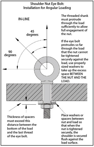
- Always use shoulder nut eye bolts (or machinery eye bolts) for angular lifts.
- For angular lifts, adjust Work Load as follows:
Direction of Pull (in-line) | Adjusted Work Load | 45 degrees | 30% of Work Load Limit | 90 degrees | 25% of Work Load Limit |
| - Never undercut eye bolt to seat shoulder against
the load. - Always countersink receiving hole or use washer with sufficient I.D. to seat shoulder.
- Always screw eye bolt down completely for proper seating.
- Always tighten nuts securely against the load.
| Table 1 In-Line Load | Size (Inches) | Work Load Limit (Lbs.) | 1/4 | 650 | 5/16 | 1,200 | 3/8 | 1,550 | 1/2 | 2,600 | 5/8 | 5,200 | 3/4 | 7,200 | 7/8 | 10,600 | 1 | 13,300 | 1-1/8 | 15,000 | 1-1/4 | 21,000 | 1-1/2 | 24,000 | 1-3/4 | 34,000 | 2 | 42,000 | 2-1/2 | 65,000 |
|
| |  | - Loads may slip or fall if proper eye bolt assembly and lifting procedures are not used.
- A falling load may cause serious injury or death.
- Read and understand these instructions and follow all eye bolt safety information presented here.
- Read, understand and follow information in diagrams and charts below before using eye bolt assemblies.
|
| 
| Table 2 In-Line Load | Metric Size | Work Load Limit (Kgs.) | M6 | 200 | M8 | 400 | M10 | 640 | M12 | 1,000 | M16 | 1,800 | M20 | 2,500 | M24 | 4,000 | M27 | 5,000 | M30 | 6,000 | M36 | 8,500 | M42 | 14,000 | M48 | 17,300 | M64 | 29,500 |
|
| Regular Nut and Shoulder Nut Eye Bolt-Installation for In-Line Loading. | 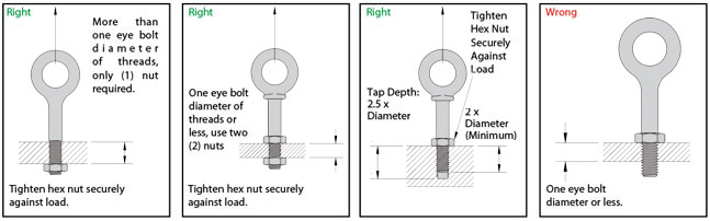
| OPERATIONAL SAFETY CONSIDERATIONS | - Always stand clear of load.
- Always lift load with steady, even pull – do not jerk.
- Always apply load to eye bolt in the plane of the eye,
not at an angle.
| | - Never exceed the Work Load Limit of the eye bolt, see Tables I & 2.
- When using lifting slings of two or more legs, make sure the loads in the legs are calculated using the angle from the vertical to the leg and properly size the shoulder nut or machinery eye bolt for the angular load.
|  | |  | | | MACHINERY EYE BOLT- INSTALLATIONS FOR IN-LINE AND ANGULAR LOADING. |
Machinery Eye Bolts are primarily intended to
be installed into tapped holes.
- After the loads on the eye bolts have been calculated, select the proper size eye bolt for the job.
For angular lifts, adjust Work Load Limit as follows:
Direction of Pull (In-Line) | Adjusted Work Load | 45 Degrees | 30% of Work Load Limit | 90 Degrees | 25% of Work Load Limit |
- Drill and tap the load to the correct sizes to a minimum depth of one-half the eye bolt size beyond the shank length of the machinery eye bolt.
- Thread the eye bolt into the load until the shoulder is flush and securely tightened against the load.
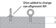
- If the plane of the machinery eye bolt is not aligned with the sling line, estimate the amount of unthreading rotation necessary to align the plane of the eye properly. Remove the machinery eye bolt from the load and add shims (washers) of proper thickness to adjust the angle of the plane of the eye to match the sling line. Use Table 3 to estimate the required shim thickness for the amount of unthreaded rotation required.
| |
Table 3 | Eyebolt Size Inches | Shim Thickness* Inches | Eyebolt Size mm | Shim Thickness* mm | 1/4 | .0125 | M6 | .25 | 5/16 | .0139 | M8 | .31 | 3/8 | .0156 | M10 | .38 | 1/2 | .0192 | M12 | .44 | 5/8 | .0227 | M16 | .50 | 3/4 | .0250 | M20 | .62 | 7/8 | .0278 | M24 | .75 | 1 | .0312 | M27 | .75 | 1-1/8 | .0357 | M30 | .88 | 1-1/4 | .0357 | M36 | 1.00 | 1-1/2 | .0417 | | | 1-3/4 | .0500 | M42 | 1.13 | 2 | .0556 | M48 | 1.25 | 2-1/2 | .0625 | M64 | 1.50 |
*Shim thickness required to change rotation 90 degrees.
 | Minimum tap depth is basic shank length plus one-half the nominal eye bolt diameter. |
|
|
|


