Sling Hitches
Slings carry their loads in one of three primary sling hitches. Most slings can be used in all three sling hitches, but some slings are designed for use in only one hitch. Slings have the largest Work Load Limit when used in a basket hitch. The vertical hitch Work Load Limit is 50% of the basket hitch. The synthetic choker hitch Work Load Limit is a maximum of 80% of the vertical hitch Work Load Limit.
Slings must be securely attached to the load and rigged in a manner to provide for load control to prevent slipping, sliding and/or loss of the load. A trained, qualified and knowledgeable user must determine the most appropriate method of rigging to help ensure load control and a safe lift.
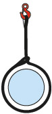
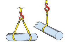
CHOKER HITCH
Sling passes through one end around the load, while the other end is placed on the hook. Load control is limited with only one sling rigged in a choker hitch. A choker hitch will never provide full 360 degree contact. For full contact use a Double Wrap Choke Hitch. See Choker Hitches. The Choke Point should always be on the sling body, not on the sling eye, fitting, base of the eye or fitting, splice or tag.
VERTICAL HITCH
One end is on the hook, while the other end is attached directly to the load. Use a tagline to
prevent load rotation.
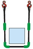
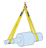
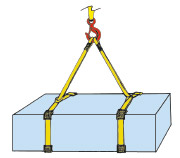
BASKET HITCH
The sling cradles the load while both eyes are attached overhead. As with the choker hitch, more than one sling may be necessary to help ensure load control.
Sling-To-Load Angle
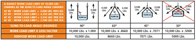
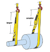
The Sling-to-Load Angle is the angle formed between a horizontal line and the sling leg or body. The Sling-to-Load Angle has a dramatic effect on sling Work Load Limits. Slings with adequate capacity to handle the “scale” weight of the load have catastrophically failed because the Sling-to-Load Angle and increased tension were not taken into account. This principle applies in a number of conditions, including when one sling is used to lift at an angle and when a basket hitch or multi-leg bridle sling is used. When selecting a sling, always consider the Sling-to-Load Angle and the tension that will be applied to the sling. As the Sling-To-Load Angle decreases, the tension on the sling leg(s) increases.
SLING-TO-LOAD ANGLE
The horizontal angle formed between the sling leg and the “top” of the load.


Illustrated right - Increased tension is magnified by any change from vertical to horizontal lifting. Increased tension is imposed on the sling leg(s) when the legs are used at angles less than 90°.
SLING ANGLE - REDUCED Work Load method
For years sling users have used angles to determine sling work load adequacy. One approach has been to determine the sling-to-load angle and multiply the work load limit by the loss factor for the specific angle. The result is the REDUCED WORK LOAD.
- Calculate the sling to load angle
- Determine the corresponding loss factor
- Multiply the work load limit by the loss factor to determine the reduced work load.
The result is the reduced work load limit.
Single angles of less than 30° should not be used, unless approved by a qualified person.
LOSS FACTOR CHART | |||
Angle "A" Degrees | Loss Factor | Angle "A" Degrees | Loss Factor |
90 | 1.000 | 55 | .8192 |
85 | .9962 | 50 | .7660 |
80 | .9848 | 45 | .7071 |
75 | .9659 | 40 | .6428 |
70 | .9397 | 35 | .5736 |
65 | .9063 | 30 | .5000 |
60 | .8660 | 25 | .4226 |
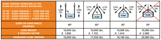
SLING ANGLE – INCREASED TENSION METHOD
Another more salient approach is to determine the INCREASED TENSION by the angle of lift. This approach has the distinct advantage of enabling the sling user to determine the required sling strength requirement. The user must first determine the angle and multiply the load weight by the tension factor for the specific angle. The result is the INCREASED TENSION or actual loading on the sling leg(s).
- Calculate the sling to load angle
- Determine the corresponding tension factor
- Multiply the load weight by the tension factor to determine the loading on the sling leg(s).
TENSION FACTOR CHART | |||
ANGLE "A" DEGREES | TENSION FACTOR | ANGLE "A" DEGREES | TENSION FACTOR |
90 | 1.000 | 55 | 1.221 |
85 | 1.004 | 50 | 1.305 |
80 | 1.015 | 45 | 1.414 |
75 | 1.035 | 40 | 1.555 |
70 | 1.064 | 35 | 1.742 |
65 | 1.104 | 30 | 2.000 |
60 | 1.155 | 25 | 2.364 |
Single angles of less than 30° should not be used, unless approved by a qualified person.
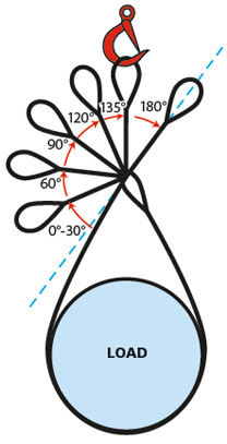
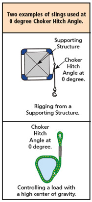
Choker Hitch Angle
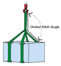
CHOKER HITCH ANGLE REDUCTION CHART | |
Choker Hitch Angle (Degrees) | Reduction Factor |
120 - 180 | 1.00 |
105 - 120 | .82 |
90 - 105 | .71 |
60 - 90 | .58 |
0 - 60 | .50 |
Center of Gravity (CG)
It is always important to rig and control the load so that stability is achieved. Determining the location of the Center of Gravity (CG) is vital to achieving load control. The CG is the point where the load weight is concentrated and is the balance point for an object. The Center of Gravity when suspended will:
1. Unless restrained, the CG will move directly under the suspension point.
2. The CG will move to the lowest point possible.
For best control, attach the slings above the CG. When this is not possible keep the CG contained with three or four sling legs or use basket or choker hitches with wraps. These measures may not guarantee load control. The user must be assured, based upon the specific application that selected methods are suitable and comply with all applicable standards and regulations.
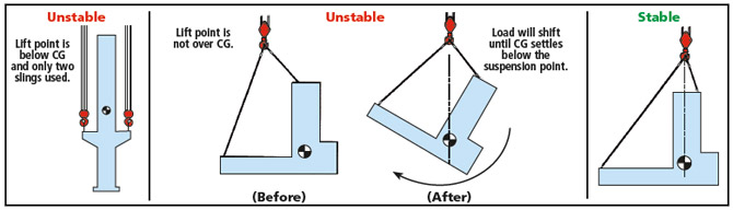
![]() Multiple factors must be taken into consideration to ensure that load control and stability are attained. A load with a “high” center of gravity can rotate in certain sling hitches.
Multiple factors must be taken into consideration to ensure that load control and stability are attained. A load with a “high” center of gravity can rotate in certain sling hitches.
Sling Tension - Leg Length/Headroom
Calculating the tension imposed on slings or individual legs of a multi-part sling system will enable the sling user to select slings with adequate Work Load Limits.
Use the following steps to calculate the tension imposed upon the individual sling legs, when you know the leg Length (L) and Headroom (H).
1) Determine the Load Factor (LAF):
Divide the leg length (L) by the headroom (H)
L ÷ H = LF
Example: 20 ÷ 15 = 1.33 Load Factor (LAF)
2) Determine the Share of the Load (SOL) for the individual sling legs:
Divide the load weight by the number of sling legs.
Load weight ÷ number of legs = Share of the Load (SOL)
Example: 12,000 lbs ÷ 3 legs = 4,000 lbs. (SOL)
3) Multiply Load Factor by the Share of the Load to determine Sling Tension
Load Factor x Share of the Load = Tension
LAF x SOL = Tension
Example: 1.33 x 4,000 = 5,320 lbs.
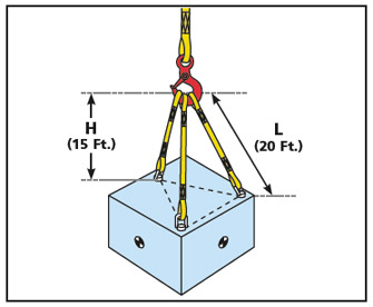
Please Note: Tension calculations are based upon:
- Sling attachment points being equidistant from the center of gravity
- Sling attachment points being equidistant to each other.
- Sling attachment points being on the same horizontal plane
- Equal sling leg lengths
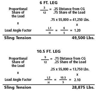
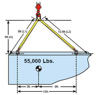
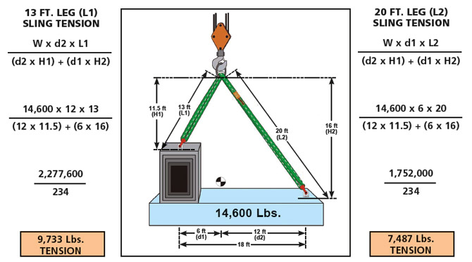
SLING TENSION - PROPORTIONAL SHARE OF THE LOAD
More complex calculations are required when the slings are not placed equidistantly from the center of gravity or when the Center of Gravity is not equidistant from the sling attachment points. The PROPORTIONAL SHARE OF THE LOAD (SOL) must be determined and multiplied by the LOAD ANGLE FACTOR (LAF) to determine SLING TENSION.
Sling tension is a function of sling length, distance between the sling attachment points and the spatial relationship between the sling attachment points and the Center of Gravity. An inverse proportional relationship exists between Distance and Share of the Load. If a sling is attached 25% of the distance from the Center of Gravity, that sling will carry 75% of the load weight. Likewise, if a sling is attached 75% of the distance from the Center of Gravity, that sling will carry 25% of the load weight.
SLING TENSION - DIFFERENT HORIZONTAL PLANES
Slings should be rigged in a manner that provides proper load control. It is dangerous to use only one sling to lift a load which tends to shift and slide out.
 (One sling is depicted for illustrative purposes only).
Ensure that lifting devices are directly over the center of gravity. If this is difficult to determine, it must be discovered by cautious experimentation or calculation. Raise the load carefully. If the load is not level, lower and correct the position of the slings until the balance point is achieved and the load does not tilt.
ADJUSTABLE BASKET HITCH
 The adjustable basket hitch allows the sling user to adjust the length of the legs to raise the load level. Adjustable hitches are particularly useful with loads having uneven load weight distribution resulting in an off-set center of gravity.
The Adjustable Basket Hitch Work Load Limit is identical to the “regular” basket hitch rating. The rating must be adjusted for the Sling-to-Load Angle. Another effective solution is an Adjustable Rope Sling featured on the following products:
- Single Leg - Adjustable Rope Slings
- Double Leg - Adjustable Rope Slings
- Adjustable Rope Slings W/Top Link
- Adjustable Rope Slings W/Top Link
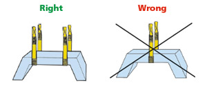
BASKET HITCHES
Inverted basket hitches are referred to as equalizing hitches because the sling is free to slip through the hook based upon the load weight distribution. Be sure to employ the “four ends down”, North to South, load engagement system.

![]() Slings “skipping” through hardware components can become damaged. Balancing the load is critical and necessary to prevent sling damage and failure
Slings “skipping” through hardware components can become damaged. Balancing the load is critical and necessary to prevent sling damage and failure
Extra care should be taken when using slings in a basket hitch to balance the load to prevent slippage.
As with the choker hitch, more than one sling may be necessary to control the load.
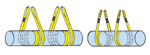
If practical, take a full wrap around the load to grip it firmly; be sure when using multiple slings that they do not cross over each other. Wrapping the load is a legitimate method of minimizing excessive sling length. Other methods, such as, twisting and knotting radically reduce sling Work Load Limits. When the load is “wrapped” the sling Work Load Limit is not increased, but load control is..
CHOKER HITCHES
The choke hitch should always be pulled tight before the lift is made, not pulled down during the lift. A sling rigged in a choker hitch (not double wrapped) does not make full contact with the load. Use multiple slings to balance the load, and wrap the load to ensure full contact. Ensure multiple slings do not cross. Choke on opposite sides of the load, if this action will not damage the load and maintain load control.
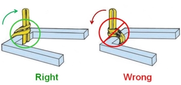
Always use a choker hitch when turning a load. If the sling is not rigged properly, the turning action will loosen the hitch, resulting in load slippage. Place sling eyes on top of the load, pointing the opposite direction of the turn. The body is then passed under the load and through both eyes. Blocking should be used to protect the sling and facilitate removal. Basket hitches should not be used to turn a load. Always downgrade the choker Work Load Limit when the angle of choke is less than 120°.
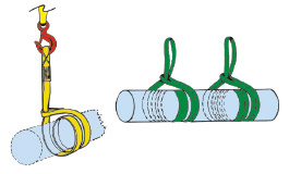
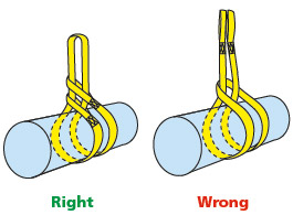
For a tighter choke hitch, which provides full, 360° contact with the load, take a full wrap around the load before choking the sling. Ensure that multiple slings do not cross. When the load is “wrapped” the sling Work Load Limit does not increase, but load control does.
Please note:
One sling is depicted for illustrative purposes only.
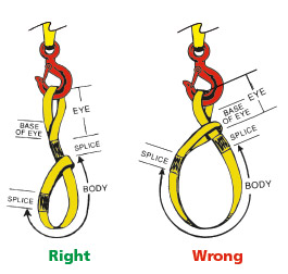
The sling should be of sufficient length to ensure that the choke action is on the sling body, never on the sling splice, fittings, tag, eye or at the base of the sling eye or fitting.
ADJUSTABLE HITCH
 The Adjustable Hitch allows the sling user to adjust the length of the legs to raise the load level. Adjustable hitches are particularly useful with loads having uneven load weight distribution resulting in an off-set center of gravity. The Work Load Limit for the Adjustable Hitch is identical to the “normal” Vertical Work Load Limit. The Adjustable Hitch works reasonably well on narrow web slings (1 and 2 in. widths) and roundslings rated at less than 7000 Lbs. choker.
DOUBLE CHOKER HITCH
 The Double Choker Hitch if applied properly will facilitate equalization of the loading on the sling legs over the lifting hardware. If applied improperly, one of the legs will share a greater portion of the load and equalization will not occur. The Double Choker Hitch Work Load Limit is twice the regular Choker Hitch Work Load Limit.


