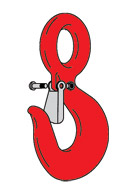
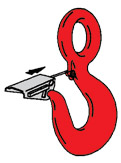
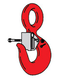
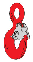
Place hook at approximately a 45 degree angle with the cam up. | Position coils of spring over cam with legs of spring pointing toward point of hook and loop of spring positioned down and lying against the hook. | Position latch to side of hook points. Slide latch onto spring legs between lockplate and latch body until latch is partially over hook cam. Then depress latch and spring until latch clears point of the hook. | 4. Line up holes in latch with hook cam.
5. Insert bolt through latch, spring and cam.
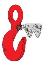
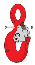
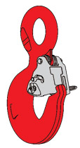
6. Tighten self-locking nut on one end of bolt. | For Personnel Lifting: With latch in closed position and rigging resting in bowl of hook, insert bolt through latch and secure with nut and cotter pin. When bolt, nut and cotter pin are not being used, store them in a designated place upon the personnel platform. |